On a mechanised spread the shielding gas system is the only part of the welding package that nobody owns. The machine is commissioned, the procedure is qualified, the operator is certified, the rail is aligned – and the regulator was last set by whoever opened the valve at the end of the previous shift. Then porosity appears on joint three hundred and forty, the automatic ultrasonic run flags it, and the investigation begins with the welding machine, which is usually innocent.
This article treats gas as an engineering system rather than a consumable: purity, flow rate, purge volume, delivery architecture, wind exposure, and the mechanical integrity of the gas train. It covers all four machine families used on pipeline work – the single-torch DW-EW-I, the dual-torch DW-EW-II, the battery and servo internal welders DW-EH48/56 and DW48/56-8H-D, and automatic TIG. Every machine figure quoted below comes from published product data. Where no product data exists a value is given as general industry guidance and labelled as such, because a supplier who invents a dew point is worse than one who admits the procedure governs.
Why gas faults are misdiagnosed as machine faults
Gas failures do not announce themselves. They produce defects that look electrical, mechanical or metallurgical, and the defect signature usually points at the wrong subsystem. The table below is the mapping we use on commissioning support calls; it resolves a large share of porosity complaints without touching a single welding parameter.
| Defect signature | Gas-side cause | First check |
|---|---|---|
| Scattered porosity across the cap, random distribution | Moisture or oil carried through the gas train; contaminated regulator seat | Drain traps, dew point, hose replacement history |
| Porosity concentrated at arc start and stop | Pre-flow too short, post-flow cut off, gas surge at strike | Gas delay settings, solenoid response time |
| Wormhole or tunnel porosity at the root | Purge below target, oxygen still high inside the chamber | Oxygen meter reading inside the purge, not at the regulator |
| Dark oxidised root, heat tint on stainless | Purge lost mid-pass, dam displaced by a pressure surge | Dam anchorage, purge pressure versus flow |
| Lack of sidewall fusion on one side only | Asymmetric flow from the second torch, cross-draught between arcs | Torch angle, individual flow per torch, wind direction |
| Arc instability and heavy spatter | Flow set too high, turbulent jet entraining ambient air | Flowmeter against nozzle diameter, nozzle condition |
| Porosity only in the morning or after rain | Condensation inside manifold or hose | Water trap, manifold drain, cylinder storage |
| Porosity recurring at one clock position | Wind ingress at a specific point of the circumference | Windbreak placement, shelter coverage |
Gas selection: what the process actually demands
Gas choice is a procedure decision, not a purchasing decision, and it differs between the root pass and the fill. The matrix below summarises the families normally seen on pipeline work. It is general industry guidance for orientation only – the qualified welding procedure specification governs, and no gas mixture in this table overrides a procedure qualification.
| Process and machine | Gas family in common use | Why | What to record daily |
|---|---|---|---|
| Single-torch external GMAW, fill and cap, carbon steel | Argon with 15-25 percent CO2; straight CO2 on heavy wall where penetration dominates | Balance between penetration, spatter and bead profile | Mixture identity, cylinder batch, flow per torch |
| Dual-torch external GMAW | Same families, but each torch needs its own regulated flow | Two arcs consume roughly twice the volume and interact aerodynamically | Individual flow for torch A and torch B, not a single manifold reading |
| Internal welder root, carbon steel | Lower CO2 content than the fill passes, to keep the root clean and reduce oxidation | The root is the surface that never gets cleaned afterwards | Cylinder residual pressure, purge oxygen level |
| Automatic TIG, carbon and stainless | Argon at high purity; helium addition for thick wall and high thermal conductivity; argon with hydrogen for austenitic stainless only | Arc stability, penetration and root colour are all gas-driven in TIG | Purity grade certificate, pre-flow and post-flow seconds |
| Duplex and super duplex root | Argon with a controlled nitrogen addition | Nitrogen supports the austenite balance in the root; omitting it risks a ferrite-rich, brittle root | Nitrogen addition confirmed against the procedure |
Four machine families, four gas duties
The machines differ less in how much gas they use than in where the gas has to reach. That single difference explains why the same cylinder and the same regulator can be perfectly adequate on one machine and a defect generator on another.
| Machine | Gas duty | Demand profile | Characteristic failure |
|---|---|---|---|
| DW-EW-I single-torch external | Nozzle shielding only, at the torch | Steady, one torch, one flow setting that may change with clock position | Flow set once at the top of the joint and never revisited as the carriage travels |
| DW-EW-II dual-torch external | Two independent nozzle shields plus inter-arc shielding | Double volume, two points of regulation, cross-flow between arcs | One manifold feeding two torches; the far torch starves while the near one looks correct |
| DW-EH48/56 battery internal welder | Torch shield inside the pipe plus local root protection, from an onboard 30 L cylinder | Burst demand per unit across 8 welding units, short arc time of 90 seconds or less | Cylinder emptied mid-joint because consumption per joint was never measured |
| DW48/56-8H-D servo internal welder | Same as above with 8 units and a 120 second pass | Slightly longer arc time, wire of 0.9 to 1.2 mm, same onboard supply logic | Flow shared unevenly across the 8 units, so one segment of the root runs lean |
| Automatic TIG | Nozzle shield, trailing shield and chamber purge | High purity, low flow, long pre-flow and post-flow | Post-flow cut to save gas, leaving the crater oxidised |
Single torch: one nozzle, one setting, and the temptation to leave it
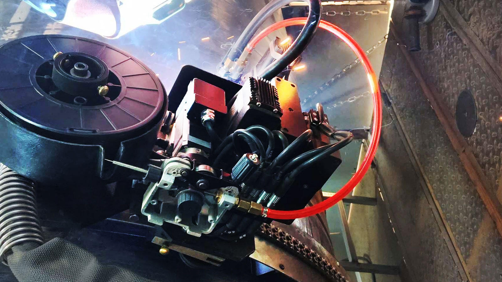
The DW-EW-I runs one arc from a light carriage on a perforated steel rail, with a single gear-rack drive that eliminates lost motion and a parameter programme that changes with welding position around the circumference. On gas, this machine is the easiest of the four to control and the easiest to neglect: one torch means one flow setting, and one flow setting means nobody revisits it. The risk is positional rather than volumetric. If the joint is welded in a shelter at the bottom and in open wind at the top, the same regulator setting produces a shielded pool at six o clock and a turbulent, air-entraining jet at twelve.
The practical countermeasure is a second flow check at the change of clock position, timed to the parameter change the machine already performs automatically. The machine adjusts current, voltage and travel speed by position because that is what consistent all-position welding requires; the gas deserves the same treatment, and the touchscreen procedure storage makes it easy to record which flow belongs to which segment.
Dual torch: twice the demand and the problem of balance
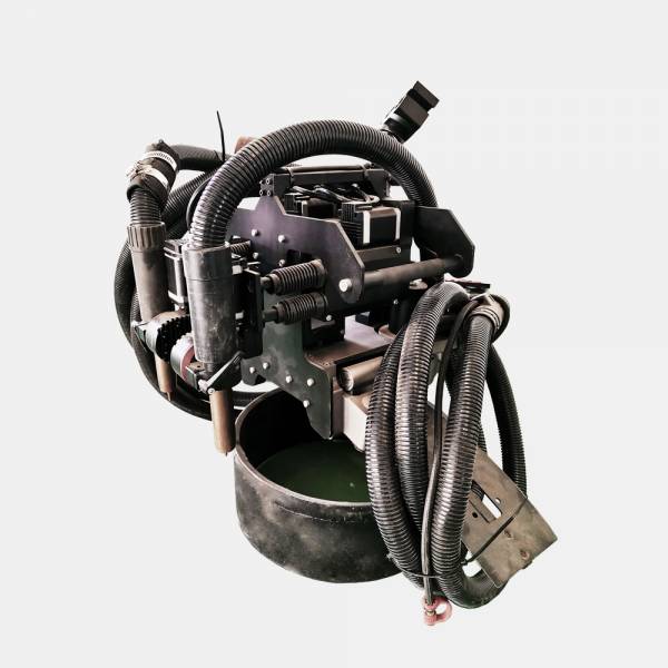
The DW-EW-II runs two arcs simultaneously in straight or angular oscillation, with arc tracking that corrects deviation along the groove and digital communication between the power sources and the control cabinet. Gas behaviour changes character here. Two arcs at close spacing create a cross-flow between them, and the second arc sees gas that the first has already heated, ionised and pushed sideways. A single manifold with a single regulator feeding both torches will almost always deliver unequal flow, and the symptom is not porosity but a one-sided lack of fusion that gets attributed to torch angle or to the tracking system.
Regulate each torch separately, measure each torch separately, and record the two numbers separately. This is not bureaucracy: with two arcs the volume demand is roughly double, and a manifold sized for one torch will pass acceptance on a short test joint and fail on the four hundredth because the regulator has drifted and nobody can tell which torch moved. The multi-channel process data storage on this machine exists precisely so that the verified combination can be recalled rather than reconstructed.
Internal welder: the 30 litre cylinder and a root shielded from inside
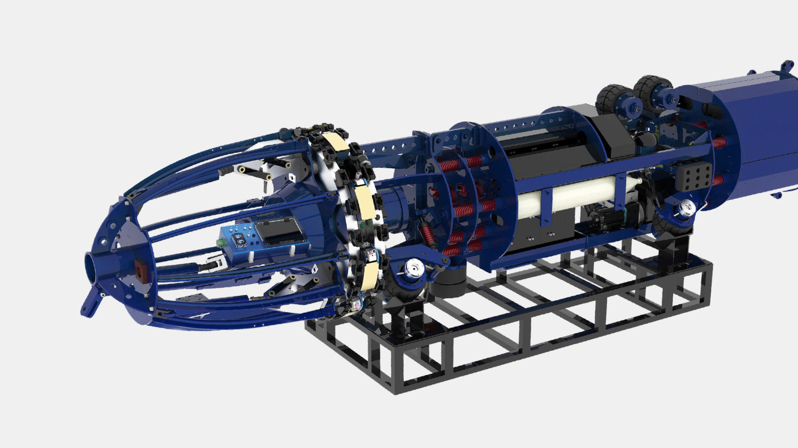
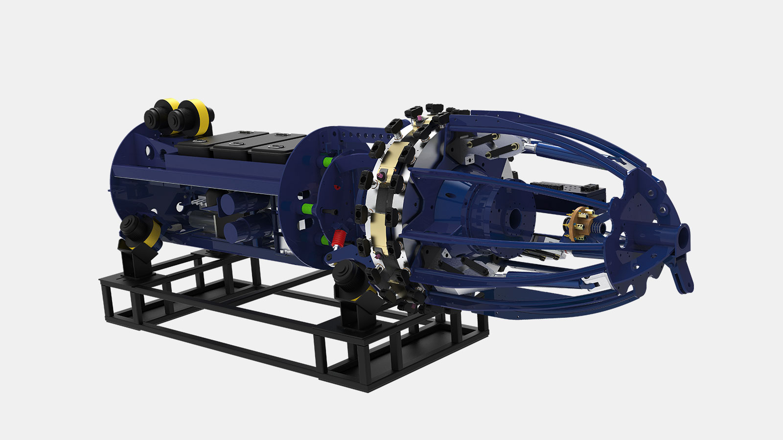
Both internal machines carry their own gas supply, and the DW-EH48/56 states a 30 litre shielding gas cylinder in its published specification. That number is the whole gas argument in one line. Thirty litres is a fixed, finite, mobile quantity, and it must protect eight welding units through a root pass completed in 90 seconds or less on a machine that weighs 2950 kg and works from minus 40 to plus 65 degrees Celsius at altitudes up to 4000 metres.
The engineering consequence is that consumption per joint has to be known before mobilisation, not discovered on site. Unlike an external welder fed from a manifold, there is no reserve to draw on and no one to call: when the cylinder empties at unit six, the root stops, and the joint is cut out. Measure litres per joint during the trial welds, multiply by the planned joint count with a margin for purge and leak allowance, and treat cylinder changes as a scheduled operation rather than an emergency.
The second function is less obvious. Because the torch is inside the pipe, the internal machine shields the root from the inside, which is where oxidation actually matters: the root surface is never cleaned afterwards, never inspected by eye, and is the surface an intelligent pig will see for the next thirty years. Local shielding from inside is far more efficient than purging an entire pipe length, and it is the reason an internal root pass can hold a clean root at a fraction of the gas that an external TIG root would need for the same joint.
| Gas-relevant point | DW-EH48/56 | DW48/56-8H-D |
|---|---|---|
| Published gas supply | 30 L shielding gas cylinder onboard | Onboard supply, same principle |
| Welding units | 8 | 8 |
| Arc time per pass | 90 seconds or less | 120 seconds or less |
| Pipe range | Phi 1219 to 1422 mm | Phi 1219 to 1422 mm |
| Wall thickness | 10 to 35 mm | Procedure dependent |
| Expansion pressure | 5 to 7 MPa hydraulic | 5 to 7 MPa hydraulic |
| Machine mass | 2950 kg | 2400 kg |
| Environment | Minus 40 to 65 C, altitude up to 4000 m, humidity up to 90 percent | Minus 50 to 65 C, altitude 0 to 3500 m, slope up to 30 degrees, 5D and 6D bends |
| Consumable wire | Procedure dependent | 0.9 to 1.2 mm |
Automatic TIG: the gas is the process
In TIG the gas is not a support function, it is the process. Arc stability, penetration shape, weld bead colour on stainless and the acceptability of the root all follow from gas purity and from the timing of pre-flow and post-flow. The characteristic site failure is economic rather than technical: post-flow is shortened to save argon, the crater oxidises, and the joint is rejected for a defect that twelve seconds of gas would have prevented.
Automatic TIG also has no separate published data sheet in our range, and we do not manufacture numbers to fill the gap. Acceptance and gas settings follow the qualified procedure, and the machine is specified against the joint rather than against a gas table. Where TIG earns its cost – small diameter, thick-wall root, dissimilar joints, and any location where a root defect means a cut-out – the gas bill is the cheapest line in the comparison.
Flow, purge volume and the arithmetic of a shielded root
Purge is the one part of gas management that can be calculated before mobilisation rather than learned by rejection. Three quantities matter: the volume to be displaced, the number of volume exchanges required to reach the target oxygen level, and the achievable flow. In symbols:
- Chamber volume: V = (pi / 4) x D squared x L, where D is internal diameter and L is the dammed length between purge dams.
- Gas required: G = V x n, where n is the number of chamber exchanges, typically five to eight for a carbon steel root and more for stainless.
- Purge time: t = G / Q, with Q the purge flow expressed in the same units per hour.
- Verification by instrument, not by time: oxygen at or below 0.1 percent for carbon steel root, and at or below 50 parts per million for stainless and duplex. These are general industry targets, not product values.
| Nominal diameter | Internal volume per metre | Purge volume, 0.6 m dammed length | Gas at five exchanges | Time at 60 L per minute |
|---|---|---|---|---|
| 219 mm | 0.038 m3 | 0.023 m3 | 0.11 m3 | about 2 minutes |
| 508 mm | 0.203 m3 | 0.122 m3 | 0.61 m3 | about 10 minutes |
| 813 mm | 0.519 m3 | 0.311 m3 | 1.56 m3 | about 26 minutes |
| 1016 mm | 0.811 m3 | 0.486 m3 | 2.43 m3 | about 41 minutes |
| 1219 mm | 1.167 m3 | 0.700 m3 | 3.50 m3 | about 58 minutes |
| 1422 mm | 1.588 m3 | 0.953 m3 | 4.76 m3 | about 79 minutes |
Read the last column and the reason for internal root welding becomes arithmetic rather than preference. Purging a 1422 mm joint with external dams costs roughly 79 minutes and 4.8 cubic metres of argon per joint before a single arc is struck. Shielding the same root from the inside with the torch that is already in the pipe removes almost all of it. This is the gas-side version of the argument that also shows up in cycle time: the internal machine does not merely weld faster, it deletes an operation that used to sit in front of the weld.
Gas delivery architecture on a remote spread
How the gas arrives matters as much as how much arrives. The table below compares the supply options normally evaluated for a long-distance pipeline job; the right answer changes with joint count, distance to the nearest supplier and whether the section is accessible by road.
| Supply option | Practical capacity | Logistics implication | When it fits | Main risk |
|---|---|---|---|---|
| 40 L cylinders, individual | Small, one or two shifts per cylinder | Frequent handling, high residual pressure losses | Short sections, tie-ins, repair work | Cylinder swap interrupts the pass |
| Cylinder bundles with manifold | Medium, several days | One delivery point, regulated distribution | Standard spreads with road access | Single point of failure for the whole spread |
| Dewar or liquid vessel | Large, weeks of supply | Heavy, needs a fixed location and venting discipline | High-consumption spreads, TIG-heavy work | Vent losses if idle; frost and icing on fittings |
| On-site mixing or generation | Continuous, no deliveries | Requires power and maintenance competence | Very large projects, remote sections | Purity drift undetected without analysis |
| Bulk tank with vaporiser | Very large | Capital installation, fixed footprint | Pipeline spreads above a few hundred joints per week | Not movable when the spread moves |
Wind, and why a shelter is a welding accessory
Every shielding calculation assumes still air. Field gas decisions are made in moving air, and the discrepancy is where a large share of unexplained porosity originates. Wind does not merely dilute the shield; above a threshold it breaks the laminar envelope and the jet starts entraining ambient air, which is why increasing flow beyond that point makes defects worse rather than better.
| Condition | What happens to the shield | Action |
|---|---|---|
| Still air, indoor or sheltered | Nominal performance at the specified flow | No adjustment; verify flow at the nozzle |
| Light breeze, under 2 m per second | Minor dilution, edge oxidation possible | Increase flow modestly, close the shelter |
| Moderate wind, 2 to 5 m per second | Envelope unstable at the upwind side of the joint | Windbreak on the windward side, verify with a flow check at the joint |
| Strong wind, above 5 m per second | Laminar envelope lost, turbulence entrains air | Stop or fully enclose; raising flow will not recover the shield |
| Wind plus low temperature | Combined dilution and rapid cooling, risk of lack of fusion | Enclosure plus preheat verification, not gas adjustment |
Gas train integrity: the discipline that costs nothing
Half of all gas defects are mechanical, not metallurgical. A regulator that has drifted two tenths of a bar, a hose with a pinhole behind the clamp, a water trap nobody drained – none of these appear in a welding parameter record and all of them appear in a radiograph. The following routine takes ten minutes at the start of a shift and is the cheapest quality measure on the spread.
- Leak-test the regulator outlet and every joint in the gas train with soap solution, at working pressure, before the first arc.
- Record static pressure and dynamic flow. A flow that drifts during a pass without a valve change is a leak, not a gauge error.
- Drain water traps before the shift and again after rain or a temperature drop through dew point.
- Purge hoses for three to five seconds before the first weld of the shift, with the outlet pointed away from the joint.
- Never use one hose for two gases. Argon and argon mixtures leave no colour, so a mis-connected hose is invisible until the root is inspected.
- Check flowmeter calibration against a spare unit on a rotating schedule, not only when a defect appears.
- Inspect the nozzle for spatter blockage every shift. The flowmeter sits upstream of the blockage and will happily report a correct flow while the nozzle is half closed.
- Cap cylinder valves and fittings whenever a line is disconnected, including a lunch break on a dusty site.
- Record cylinder change time and residual pressure; a trend of rising residual pressure means consumption is falling, which is itself a warning.
- Replace a damaged hose. Tape is a pressure-retaining device only in the imagination.
Diagnostics: reading a gas problem from the weld
| Observation | Probable cause | Check | Corrective action |
|---|---|---|---|
| Porosity in the first 20 mm of every pass | Pre-flow too short for the hose length | Time the gas delay with a stopwatch | Extend pre-flow; check solenoid response |
| Porosity only on the second torch of a dual machine | Flow imbalance at the manifold | Measure each torch separately at the nozzle | Independent regulation per torch |
| Root grey to black, no metallic sheen | Purge oxygen above target | Oxygen meter inside the chamber | Extend purge, check dam sealing |
| Heat tint progression along the joint | Purge decaying as the pass advances | Purge flow during the pass, not before it | Maintain purge flow through the pass |
| Bead width varying with clock position | Flow varying with position or wind exposure | Flow at the nozzle at several positions | Position-specific flow, windbreak |
| Cylinder emptying faster than forecast | Leak downstream of the regulator | Soap test on every fitting | Repair before the next joint |
| Spatter increasing with no parameter change | Flow too high, turbulent jet | Flow against nozzle diameter | Reduce flow, check nozzle bore |
| Same joint passing then failing on re-test | Marginal purge, sensitive to ambient conditions | Ambient temperature and humidity log | Tighten purge target, add margin |
Ten-point pre-shift gas checklist
- Cylinder identity and mixture confirmed against the procedure, not against memory.
- Residual pressure adequate for the planned joint count, with a margin for purge.
- Regulator leak-tested and locked at the verified setting.
- Flow verified at the nozzle, not at the regulator outlet.
- Nozzle clean, bore unobstructed, correct diameter for the joint.
- Hose inspected end to end, no cuts, no taped repairs, correct gas.
- Water traps drained and manifold purged.
- For internal machines: litres per joint known, 30 L cylinder level recorded, change scheduled.
- For TIG: pre-flow and post-flow seconds confirmed, trailing shield fitted where specified.
- Windbreak or enclosure positioned, and the weather forecast read before the shift plan is issued.
Frequently asked questions
Does higher gas flow always mean better protection?
No, and past a threshold it means worse protection. Beyond the laminar range the jet becomes turbulent and entrains ambient air into the pool. The correct flow is the one that produces a stable envelope at the nozzle for the nozzle diameter in use, verified with a flowmeter and confirmed by root appearance, not the highest number the regulator will deliver.
Can the internal welder use the same gas as the external passes?
It can share the family but not usually the mixture ratio. The root is the surface that is never cleaned afterwards, so the root pass normally runs leaner in oxidising additions than the fill and cap. The published 30 litre onboard cylinder on the DW-EH48/56 means the choice has a direct logistics consequence: a richer or higher-flow mixture shortens the interval between cylinder changes on a machine that may be several kilometres from the supply point.
How do we know the purge is good enough without an oxygen meter?
You do not, and this is the one place where we recommend refusing to proceed without an instrument. Time-based purge rules assume a dammed volume, a sealing quality and a flow that are all estimates. An oxygen meter costs less than one cut-out on a large diameter joint, and the reading inside the chamber is the only evidence that survives an audit.
Which gas decision has the largest effect on total cost?
Matching the machine to the joint so that the root does not need purging at all. Beyond that, eliminating rework: a single cut-out on a 1422 mm joint consumes more gas, wire, time and heating energy than a month of small leaks across an entire spread.
Conclusion
Shielding gas is the cheapest component of a pipeline welding package and the one that most often decides whether a joint passes. Treat it as a system with four parts: selection driven by the qualified procedure, delivery architecture sized to the joint count, purge arithmetic calculated before mobilisation rather than discovered on site, and a gas train maintained with the same discipline as the welding machine. The single-torch machine asks for position-aware flow; the dual-torch machine asks for two independent regulated supplies and two measurements; the internal machines, with their 30 litre onboard cylinder and their root shielded from inside, ask for consumption per joint to be known in advance; and automatic TIG asks for pre-flow and post-flow to be treated as part of the process rather than as a gas bill.
Get those four right and most porosity investigations end at the regulator instead of at the welding machine – which is where they were always going to end.
Beijing Anjie Weida Technology Co., Ltd. (DENOH Group) | Tel: 010-86468776 | Email: sales@denohgroup.com | WhatsApp/WeChat: 13521628344 | Contact: /contact/