Most automatic welding problems on a pipeline spread are not machine failures. They are mismatch failures. The carriage runs, the arc strikes, the parameters load from the touch screen — and the repair rate still climbs, because the line pipe in front of the machine sits outside the window the machine was bought for. Outside diameter, wall thickness, steel grade and pipe-end condition together define that window, and they define it long before anyone chooses between a single torch and a dual torch.
This guide works through the three-dimensional envelope that governs equipment selection for the pipeline automatic welding range — the single-torch external welder, the dual-torch external welder, the lithium and flexible internal welders, and automatic TIG root welding — and sets out how to confirm, before mobilisation, that the machine and the line actually belong together.
Why the Process Window Decides Whether Automatic Welding Pays
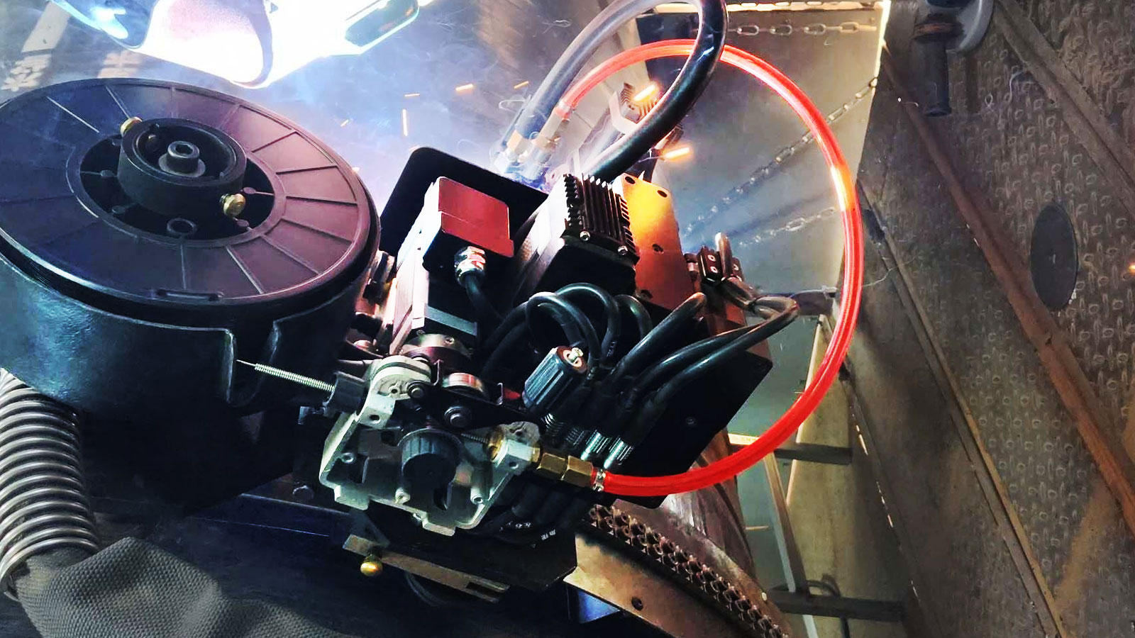
Automatic welding earns its money by being repeatable. Repeatability is only possible inside a defined process window: a range of diameter, wall thickness, material and fit-up within which the same programme produces the same joint. Step outside it and the technology does not fail dramatically — it degrades quietly. Travel speed is no longer matched to the groove, the arc does not reach the root shoulder, the interpass temperature drifts, and the defects that appear are the expensive kind: lack of fusion, incomplete penetration and hydrogen-assisted cracking, all of which are found by NDT rather than by eye.
The commercial argument is therefore simple. The cost of a machine is fixed; the cost of a mismatch is paid on every joint, through repairs, cut-outs and lost spread days. Establishing the window first is what turns an equipment purchase into a process capability.
Four dimensions define that window, and they interact rather than act independently:
| Dimension | What it changes in the process | Where it usually bites back |
|---|---|---|
| Outside diameter | Track curvature and track fit; internal mechanism reach; number of welding units that can be carried; travel speed | Out-of-round pipe and small diameters cause track slip and inconsistent travel |
| Wall thickness | Groove geometry, number of passes, heat input per pass, shielding gas consumption, shrinkage and distortion | Burn-through and excess reinforcement on thin wall; lack of fusion and hydrogen risk on thick wall |
| Steel grade and chemistry | Carbon equivalent, preheat and interpass limits, heat input ceiling, hydrogen control and HAZ hardness | Cold cracking and loss of HAZ toughness where preheat or heat input is not controlled |
| Pipe end condition and fit-up | Root gap, high-low and ovality the machine must absorb before the arc produces a sound root | Root defects that propagate into fill passes, and cut-outs at the tie-in |
Diameter: Why the Two Ends of the Range Use Different Machines
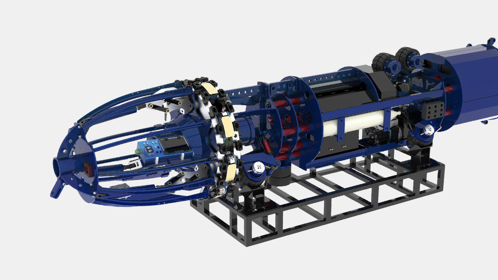
The external welding machines cover the full range. Both the single-torch and the dual-torch units are specified for Φ219–Φ1422 mm, using a split ring track and a light carriage that can be fitted to any diameter in that band. The internal welders are different: both the lithium machine (DW-EH48/56) and the flexible machine (DW48/56-8H-D) are specified for Φ1219–Φ1422 mm.
That is not a marketing limit, it is geometry. An internal welder has to be introduced into the pipe, centred by hydraulic expansion shoes and then rotate a head carrying eight welding units around the inside of the joint. Below roughly 48 inches there is simply not enough internal volume for the mechanism and for the operator access needed to place it. Small-diameter lines are therefore root-welded from the outside or by a different process altogether.
The practical consequence is a two-tier selection rule:
- Small and medium diameters (roughly Φ219–Φ800 mm). External welding only. A single-torch machine is the workhorse — shortest set-up, lowest cost per metre of track, best suited to pre-fabrication shops and mixed-diameter work.
- Large diameters (roughly Φ1016–Φ1422 mm). External fill and cap with one or two torches, plus an internal welder for the root pass. Root welding from inside removes the most defect-prone pass from the outside and lets the external carriages concentrate on fill and cap.
- The 30 inch to 48 inch transition band. Where the line crosses Φ800–Φ1219 mm, decide by pass and groove economics rather than by habit: the internal welder is not available, so the root strategy has to be settled with the external machines.
Track fit deserves separate attention in this discussion, because it is the single most common cause of poor-looking automatic welds on small diameter pipe. A split toothed steel track clamped to an oval pipe inherits that ovality, and the carriage then rides a variable stand-off. On thin-wall small diameter line pipe, measure ovality during set-up and correct with the internal line-up clamp before committing to the pass.
Wall Thickness: Pass Count, Heat Input and the 10–35 mm Band
Wall thickness converts directly into passes, and passes convert into time, gas and accumulated heat. The lithium internal welder is specified for a wall thickness range of 10–35 mm, which brackets the great majority of transmission and gathering line wall thicknesses in the Φ1219–Φ1422 mm diameter class.
Thick wall and thin wall fail in opposite directions, and the machine settings have to reflect that:
- Thick wall (above roughly 20 mm). More passes, more interpass time, higher accumulated heat and a real risk of hydrogen-assisted cracking in the HAZ if preheat falls away between passes. Heat input has to be balanced against a heat input ceiling that protects toughness.
- Thin wall (below roughly 12 mm). Burn-through and excess reinforcement become the dominant risks. Travel speed, wire feed and root protection have to be tight, and fit-up tolerance is far less forgiving than on heavy wall.
- Mixed wall at tie-ins and transitions. The wall thickness step concentrates stress and heat sink difference; these joints should be treated as their own procedure, not as a variant of the mainline pass.
| Wall thickness band | Typical groove and pass structure | What the machine must hold |
|---|---|---|
| 10–14 mm | Single-V or compound bevel; root plus two to three fill / cap passes | Tight energy control to avoid burn-through; precise stand-off; consistent travel speed |
| 14–20 mm | Compound bevel; root plus four to six passes | Pass-to-pass parameter switching, interpass discipline, stable arc at mid-wall |
| 20–28 mm | Compound or U preparation; root plus seven to ten passes | Heat input management, torch cooling and duty cycle, preheat maintenance between passes |
| 28–35 mm | U preparation or narrow gap; root plus ten or more passes | Duty cycle and thermal management of both machine and power source; distortion control |
Shielding gas is a thickness bill as well as a diameter bill. The lithium internal welder carries a 30 litre protective gas cylinder on board, which is an advantage in the field but also a budget: the number of joints between refills scales with pass count and with the flow rate required for the groove geometry. On thick wall work, calculate gas consumption per joint from the procedure rather than from the diameter, then size the refill plan accordingly.
Steel Grade: Carbon Equivalent, Preheat and Low-Hydrogen Discipline
The third dimension is the one most often left to site habit. Line pipe for transmission service runs from L245 / X42 up to L555 / X80 and beyond, and the property that governs weldability is not the yield strength itself but the carbon equivalent and the resulting risk of a hard, crack-susceptible heat affected zone. Higher grades require three things to be controlled simultaneously: preheat, hydrogen input and heat input.
| Grade band (typical) | Weldability consideration | Hydrogen control emphasis |
|---|---|---|
| L245–L290 (X42–X46) | Low carbon equivalent; generally straightforward; cold-weather preheat is the main issue | Standard consumable and cleanliness discipline |
| L320–L360 (X52–X56) | Intermediate carbon equivalent; preheat becomes a real parameter rather than an optional step | Dry consumables, clean bevel, no damp groove |
| L390–L450 (X56–X65) | Higher strength; HAZ hardness and toughness both need attention; heat input ceiling becomes relevant | Strict low-hydrogen practice, controlled electrode and wire handling |
| L485–L555 (X70–X80) | Higher carbon equivalent; tight preheat window, capped heat input, interpass temperature control | Full low-hydrogen discipline; moisture exclusion; no interrupted cooling |
Typical preheat ranges used for general guidance
The values below are conventional engineering guidance for carbon and low-alloy line pipe in the field. They are not product parameters and they do not override a project procedure: the welding procedure specification and its supporting qualification test govern, and thicker wall, higher carbon equivalent and colder ambient all push the required preheat up.
| Grade / carbon equivalent | Typical preheat guidance | Comment |
|---|---|---|
| X42–X46, CE below about 0.40 | Often none above 0 °C ambient; 10–20 °C if cold or damp | Dry the groove; remove ice, frost and surface water |
| X52–X56, CE around 0.40–0.45 | Around 50–100 °C | Preheat by induction or resistance heating rather than by flame where possible |
| X60–X65, CE around 0.45–0.50 | Around 100–150 °C | Maintain between passes; verify with contact thermometer or thermal crayons |
| X70–X80, CE above about 0.50 | Typically 100–150 °C and upwards for heavy wall | Strict low-hydrogen practice; commonly an interpass ceiling around 250 °C to protect toughness |
Two points matter more than the numbers. First, preheat has to survive the pass sequence: on a thick wall joint the first pass can be perfectly controlled and the eighth written off because the pipe cooled while the carriage was repositioned. Second, the heat input that raises productivity also coarsens the HAZ, so on high grades the economic instinct to push travel speed has to be checked against the toughness requirement in the specification.
Building the Window: WPS, Qualification and Trial Joints
The process window is not a catalogue entry, it is a documented capability for a specific project. On automatic welding this is normally established through a welding procedure specification supported by a procedure qualification record — commonly to ISO 15614-1 or ASME Section IX — carried out on the actual pipe material, diameter, wall thickness and grade combination for the line.
In practice the sequence that avoids surprises looks like this:
- Confirm the line pipe specification: diameter, wall thickness, grade, delivery condition and pipe-end form.
- Confirm the worst case in the spread, not the average — the thickest tie-in, the coldest month, the smallest radius bend.
- Weld trial joints on representative material using the machine and torch configuration that will be mobilised.
- Test the trial joints by the project NDT method and, where required, by destructive testing for hardness and toughness.
- Write the qualified parameters into the machine programme library rather than leaving them on a sheet of paper in the site office.
- Verify in production for the first joints of each shift or each new pipe batch, and record the result.
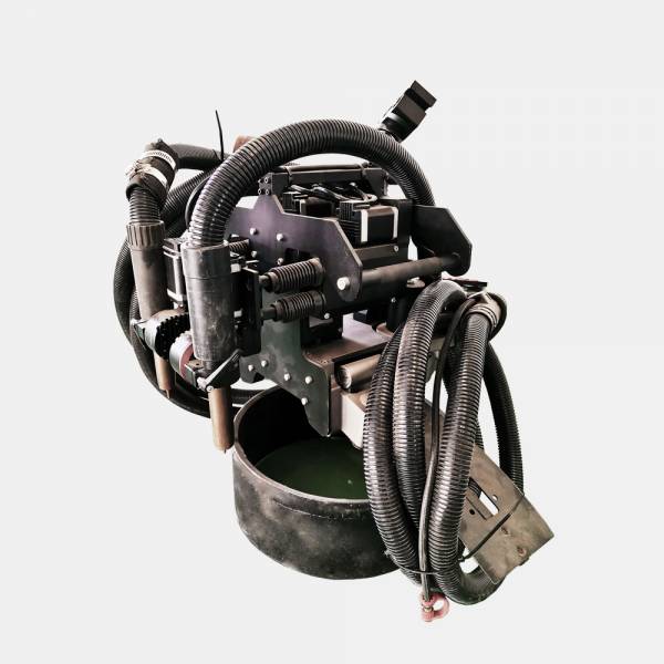
The machine side of this is easier on some models than others, and it is worth selecting deliberately. The single-torch and dual-torch external machines both provide a visual touch screen on which parameters can be set, displayed, modified and stored, with upload and download of parameter sets. The dual-torch machine extends this with multi-channel storage, recall, import and export of process data, which is what makes a library of qualified procedures practical rather than theoretical.
Machine-to-Line Selection Matrix
Bringing the three dimensions together, the matrix below summarises how the four machine types are normally deployed against line pipe parameters. It is a starting position for a selection study, not a substitute for qualification on the project material.
| Machine | Specified diameter range | Wall thickness | Position in the joint | Typical line |
|---|---|---|---|---|
| Single-torch external (DW-EW-I) | Φ219–Φ1422 mm | All project thicknesses | Fill and cap; root where internal access is impossible | Small and medium diameter lines; prefabrication |
| Dual-torch external (DW-EW-II) | Φ219–Φ1422 mm | All project thicknesses | Fill and cap, with arc auto-tracking for consistent bead placement | High-grade transmission lines; tight schedules |
| Lithium internal (DW-EH48/56) | Φ1219–Φ1422 mm | 10–35 mm | Root pass from inside; eight welding units | Large diameter transmission; remote and off-grid spreads |
| Flexible internal (DW48/56-8H-D) | Φ1219–Φ1422 mm | Large diameter wall ranges | Root pass from inside; eight welding units; compact body for bends and slopes | Mountainous and urban routes; 5/6 D bends; gradients to 30° |
| Automatic TIG root welding | Smaller and medium diameters | Thin to intermediate wall | Root pass from outside where internal access is not available | Process piping; stainless and special material; refurbishment |
Note the asymmetry that runs through the whole matrix: the internal welders are the efficient root solution for large diameter line pipe, but they are unavailable below roughly 48 inches. Everything below that threshold — which is most of the industrial and municipal pipe in the world — is decided between the single-torch machine, the dual-torch machine and automatic TIG.
Special Pipe: Clad, Coated, Weathered and Stainless
Four material situations fall outside routine line pipe practice and should be treated as their own qualification exercises:
- Internally coated or lined pipe. Coating damaged by preheating or by spatter becomes a corrosion initiation site; preheat limits are set by the coating, not by the steel, and the qualification has to be done on coated pipe.
- Clad and bimetal pipe. The root is made in the corrosion-resistant layer and the fill in the carbon steel; dilution control becomes the governing variable, and the procedure must specify which pass uses which consumable.
- Weathered and low-alloy structural steel. Chemistry varies from heat to heat; carbon equivalent must be taken from the actual mill certificates rather than from the grade name.
- Stainless and duplex. Heat input and interpass temperature are capped to protect corrosion resistance and phase balance — a constraint that pushes against the productivity instinct more strongly than any carbon steel rule.
Ten Checks Before You Commit a Machine to a Spread
- Is the diameter band confirmed against the actual line pipe, including any reduced-diameter sections?
- Is ovality and out-of-roundness measured at the work front, not assumed from the mill certificate?
- Is the wall thickness range confirmed, and is the pass and groove structure written into the procedure?
- Is the steel grade and carbon equivalent taken from the actual mill certificates?
- Has the internal welder been ruled in or out on the basis of internal volume and access, not on preference?
- Is the root strategy defined for every diameter band on the spread, including the transition band?
- Is preheat method, level and verification agreed, with a means of holding temperature between passes?
- Is the shielding gas consumption per joint calculated from the procedure, and is the refill plan sized to it?
- Is the machine parameter library populated with qualified parameter sets before the first production joint?
- Is there a defined reaction to a failed verification joint, including authority to stop the spread?
Frequently Asked Questions
Can a single machine cover the whole diameter range?
The external machines are specified across Φ219–Φ1422 mm with a split toothed track and a light carriage, so one machine can cover a wide band. What changes across that band is not the machine but the track curvature, the stand-off stability and the trial-joint requirement: each new diameter should be verified rather than assumed.
Why is there no internal welder for small diameter pipe?
Below roughly Φ1219 mm there is insufficient internal volume for the expansion mechanism and the rotating head carrying the welding units, and insufficient access to place and retrieve the machine. Root welding on smaller diameters is done from the outside or by another process.
Does a thicker wall simply mean slower welding?
Not only slower. Thicker wall increases pass count, gas consumption, interpass time and total heat input, which together affect hydrogen risk, toughness and distortion. The time cost is the visible part; the metallurgical cost is the part that shows up in hardness and impact test results.
How close to the specified limits can we work?
Design margin is not process margin. A machine offered at Φ1219–Φ1422 mm and 10–35 mm will run at the edges of that range, but the surrounding variables — ovality, grade, ambient temperature, fit-up — are what decide the outcome. Working at a limit is acceptable when it has been qualified on representative material.
Conclusion
Automatic pipeline welding is a capability, not a product. The capability exists inside a window defined by diameter, wall thickness, steel grade and pipe-end condition, and the four machine types in the ENGINE WELDER / DENVO pipeline automatic welding range cover different parts of that window deliberately: the external machines across the full diameter range, the internal machines where the diameter is large enough for a root pass to be made from inside, and automatic TIG for the smaller and special-material work where external root welding is required.
Matching the machine to the line is therefore not a stage to be compressed. Confirm the envelope, qualify the procedure on representative material, load the parameters into the machine, and verify in production. Done in that order, automatic welding delivers the repeatability it was bought for; done in any other order, it delivers a repair rate that looks like a machine fault but is not.
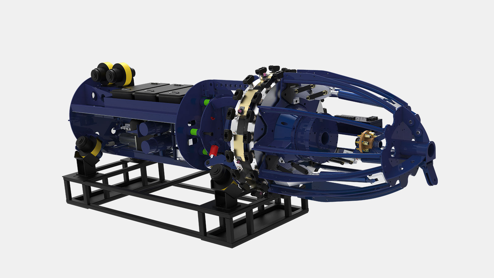
For line pipe parameter confirmation, machine selection or trial-weld planning, our engineers can review the pipe specification against the process window before you commit equipment to the spread.
Beijing Engine Welder Technology Co., Ltd. (DENOH Group)
Tel: 010-86468776 | Email: sales@denohgroup.com | WhatsApp/WeChat: 13521628344
Website: www.denohgroup.com | Contact: /contact/